Digital Visual Interface (DVI) is a popular video interface that supports high resolution digital video signal transmission. Developed by the Digital Display Working Group, DVI is now an industry standard for digital video connection.
DVI Single Link
RGB component video signals carried over 3 links – supporting a total 24 bits pixel
Pixel clock on the 4th link – supporting upto a maximum 165 MHz
Maximum resolution supported 2.75 megapixels @ 60 Hz -> Support widescreen 16:10 ratio of 2098×1211 / 4:3 ratio of 1915×1436 pixels / 5:4 ratio of 1854 x 1483 pixels.
DVI Dual Link
To support display modes that require more than 24 bits/pixel or 165 MHz pixel frequency. The second link carries the least significant bits of each pair.
Analog VGA
The wiring interface required to connect such a DVI source to a VGA monitor is shown at the end of this document.
NOTE – DVI source with connector type DVI-D do not support analog VGA monitors.
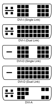
DVI Connector Types
DVI Connector Signal Name and Description
| # |
Signal_name |
Detail_Description |
DVI-I (Single) | DVI-I (Dual) | DVI-D (Single) | DVI-D (Dual) | DVI-A |
| 1 | TMDS data 2− | Digital red− (link 1) | * | * | * | * | * |
| 2 | TMDS data 2+ | Digital red+ (link 1) | * | * | * | * | * |
| 3 | TMDS data 2/4 shield | * | * | * | * | ||
| 4 | TMDS data 4− | Digital green− (link 2) | * | * | |||
| 5 | TMDS data 4+ | Digital green+ (link 2) | * | * | |||
| 6 | DDC clock | * | * | * | * | * | |
| 7 | DDC data | * | * | * | * | * | |
| 8 | Analog vertical sync | * | * | * | * | * | |
| 9 | TMDS data 1− | Digital green− (link 1) | * | * | * | * | |
| 10 | TMDS data 1+ | Digital green+ (link 1) | * | * | * | * | |
| 11 | TMDS data 1/3 shield | * | * | * | * | ||
| 12 | TMDS data 3- | Digital blue− (link 2) | * | * | |||
| 13 | TMDS data 3+ | Digital blue+ (link 2) | * | * | |||
| 14 | +5 V | Power for monitor when in standby | * | * | * | * | * |
| 15 | Ground Return for pin 14 and analog sync | * | * | * | * | * | |
| 16 | Hot plug detect | * | * | * | * | * | |
| 17 | TMDS data 0− | Digital blue− (link 1) and digital sync | * | * | * | * | * |
| 18 | TMDS data 0+ | Digital blue+ (link 1) and digital sync | * | * | * | * | * |
| 19 | TMDS data 0/5 shield | * | * | * | * | ||
| 20 | TMDS data 5− | Digital red− (link 2) | * | * | |||
| 21 | TMDS data 5+ | Digital red+ (link 2) | * | * | |||
| 22 | TMDS clock shield | * | * | * | * | * | |
| 23 | TMDS clock+ | Digital clock+ (links 1 and 2) | * | * | * | * | * |
| 24 | TMDS clock− | Digital clock− (links 1 and 2) | * | * | * | * | * |
| C1 | Analog red | * | * | * | |||
| C2 | Analog green | * | * | * | |||
| C3 | Analog blue | * | * | * | |||
| C4 | Analog horizontal sync | * | * | * | |||
| C5 | Analog ground | Return for R, G, and B signals | * | * | * |
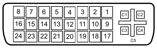
DVI Connector Pin Outs
Interface DVI-A / DVI-D type connector to a VGA monitor
The following describes the wire connection required to interface a DVI-A / DVI-D connector to a VGA monitor.
Standard DVI-VGA adaptors available in market, will include these connections
| DVI Pin # | VGA Pin & Signal |
| C1 | 1 / Red |
| C2 | 2 / Green |
| C3 | 3 / Blue |
| C4 | 13 / H-Sync |
| C5 | 5,6,7,8 / GND |
| 6 | 15 / ID3 |
| 7 | 12 / Monitor ID-0 |
| 8 | 14 / V-Sync |
| 14 | 9 / Key |
| 15 | 10 / Sync Ground |